Domestic hot water recirculation systems serve two purposes. They provide comfort and convenience and help conserve water. They maintain sufficiently heated water closer to tap so we waste less water and time before we shower, bathe, wash dishes, etc.
It’s not often in the modern world that human comfort and conservation of a precious natural resource go hand in hand but this is one of them.
Hot water recirculation systems are also part of the building code now that most states soon or will be adhering to ASHRAE 90.1 – 2010. Therefore, it is important that anyone involved in the design or installation of commercial plumbing systems understand how these systems work.
Why We Must Design to Save Water
What could have led ASHRAE, and subsequently building codes all over the U.S., to require domestic hot water recirculation systems in non-residential buildings? This relatively bold stance on water conservation is quite simply a reaction to profound water shortages throughout the world. – shortages that will only get worse as the population continues to increase.
There are some rather alarming facts about the fresh water supply that tend to go unnoticed or unacknowledged by the average citizen – particularly those of us in the southeast where we’ve been less affected by water shortages. Here are a just a few:
- As of the end of May 2014, severe to extreme drought has affected about 20% of the world
- About 34 percent of the contiguous fell in the moderate to extreme drought categories at the end of May 2014.
- The year 2013 closed as the driest year in recorded history for many areas of California, and the drought is continuing this year.
- According to a Scripps Institution of Oceanography study there is a 10% chance that Lake Mead, largest water reservoir in the United States, could be dry by 2014. Globally speaking, the numbers are more disturbing:
- More than 1 billion people worldwide lack adequate access to clean drinking water
- 2.7 billion people find water scarce for at least one month of the year.
- One in five people in the developing world lacks access to sufficient water to meet even the most basic requirements for wellbeing and child development.
- According to the United Nations, water use has grown at more than twice the rate of population increase in the last century.
- By 2025, an estimated 1.8 billion people will live in areas plagued by water scarcity, with two-thirds of the world’s population living in water-stressed regions as a result of use, growth, and climate change.
Meanwhile, we use an average of 151 gallons of water per person per day. Since water is a necessity for literally everything we hold dear, from life to the production of food and energy, the implications of the global water crisis are far reaching. Powerful arguments exists that water scarcity alone represents one of the greatest threats to global economies and even international security. After all, the population and our need for fresh water continue to grow while the amount of fresh water we have on earth stays the same.
Domestic hot water recirculation systems save water – lots of water. That’s why ASHRAE 90.1-2010 is onboard and why contractors and engineers should be onboard as well. Effective application of such systems involves a careful balance between the additional energy required to drive recirculation systems and the water they save. Over the next several blogs, we will be going over the finer points of domestic hot water recirculation system design so that you can make the most of this strategy, which will soon be a requirement in your state if it isn’t already.
Where ASHRAE 90.1 Conflicts with OSHA
When it comes to domestic hot water recirculation design, OSHA safety provisions
and ASHRAE 90.1 energy efficiency requirements have put plumbing engineers
between the proverbial rock and hard place.
In an effort to minimize the energy penalty associated with mandatory domestic hot
water recirculation, ASHRAE 90.1 has created operational parameters for these
systems. The problem is that these parameters are in direct conflict with OSHA’s
requirements for Legionella prevention.
What ASHRAE Says
As we noted in our last blog, domestic hot water recirculation is a requirement of ASHRAE 90.1 – 2010 and is on its way to becoming part of commercial building codes throughout the U.S. While recirculation is great for convenience and water conservation, it does involve additional energy usage, which is why the ASHRAE 90.1 also includes the following mandatory provisions:
- Recirculating hot water systems must be equipped with automatic time switches or other controls that can be set to switch off the usage of the temperature maintenance system during extended periods when hot water is not required.
- Temperature controlling means shall be provided to limit the maximum temperature of water delivered from lavatory faucets in public facility restrooms to 110°.
- When used to maintain storage tank water temperature, recirculating pumps shall be equipped with controls limiting operation to a period from the start of the heating cycle to a maximum of five minutes after the end of the heating cycle.
What OSHA Says
While these are all prudent measures when it comes to energy conservation, there is a problem. In the interest of Legionella prevention, OSHA has different recommendations:
- To minimize the growth of Legionella in a system, domestic hot water should be stored at a minimum of 140°
- Domestic hot-water recirculation pumps should run continuously. They should be excluded from energy conservation measures. OSHA’s position is not without basis. Legionella can survive in 122°F water and even higher in stagnant conditions where scale and sediment provide a safe haven for the bacteria. The most clear cut way to avoid this situation is to maintain the system at a higher temperature and recirculate the water continuously. A high/low flow mixing valve should be used in storage systems so the tank can be keep at 140°F to prohibit Legionella growth while providing 110°F water to the fixtures.
What’s an Engineer To Do?
All this puts plumbing engineers in the unenviable position of choosing between OSHA and ASHRAE on this particular point. Since Legionnaires’ disease continues to be among the most deadly of preventable diseases, most engineers are likely to err on the side of OSHA. Disease prevention trumps energy conservation. However, there is reason to hope that a less prohibitive solution for engineers is on the horizon.
We touched on the development of ASHRAE Standard 188, a standard of practice for facility managers/owners to prevent Legionellosis, in a previous blog. If adopted, Standard 188 will shift some of the burden of prevention from engineers to owners and facility managers by requiring them to systematically identify and address their own risks. The standard has been in the works for many years, but there is reason to believe that it may go into effect as early as 2015. Presumably, system designers will be able to refer to this standard of practice to determine if their building water system design and engineering practices should be reviewed or revised.
More on ASHRAE Standard 188
ASHRAE Standard 188 specifies certain “practices” that are the responsibility of the owner to initiate and follow through with to reduce their own risks for Legionella. It is an elaborate protocol that requires building owners to establish a team with assigned responsibilities and accountabilities with regard to Legionella control. Once identified, the team must:
- Describe how water is processed and used within the building, using process flow diagrams.
- Perform systematic analysis to identify potential hazards throughout the entire water process.
- Decide which if any hazards are significant, and if they are, determine what hazard control should be implemented.
- Establish critical control limits.
- Establish a set method for monitoring any potential hazards, along with a frequency protocol, and even corrective actions if critical control limits are violated.
- Decide how it will confirm that the plan is being properly implemented. This is indeed an extraordinary new requirement for building owners and facility managers – one that will no doubt involve a challenging learning curve. Nevertheless, it gives engineers the opportunity to decide on their own baseline preventive measures for Legionella (i.e. recirculation, temperature maintenance, etc.), while leaving it up to building owners to identify and address any further action that should be taken.
The Role of the Recirculation Pump
Whether you are thinking of installing a recirculation pump in a 3-bedroom home or designing a recirculation system for a 20-story office building, the role of the recirculation pump is always the same. Clearly, the pump is moving the water in order to keep hot water at or near the tap—but that’s really a simplified explanation of the pump’s role.
Technically, the role of the recirculating pump is to overcome the heat loss in the supply pipe – that length of pipe that stretches from the water heater outlet all the way to the farthest fixture. In most designs we are only willing to tolerate a heat loss of 10 to 20°F degrees between these two points. Whatever temperature difference your design calls for is your design ∆T. The ∆T must be known in order to complete the heat loss calculation that is required to size your pump.
Minimal Heat Loss = Small Pump
We’ll discuss recirculation pump sizing in greater detail in an upcoming blog. For
now, it’s important to understand that the pump size is determined by the supply
pipe heat loss in a no draw situation, so that first thing in the morning when
someone washes their hands at the top floor of their building, the water will be no
more that 10 or 20°F (depending on the design ∆T) cooler than the water heater
supply temperature.
How much heat loss typically occurs in a hot water system? Obviously that depends
on the length of pipe, and the more pipe the greater the heat loss. However, that
pipe is often quite small in diameter and will be insulated, so the heat loss is actually
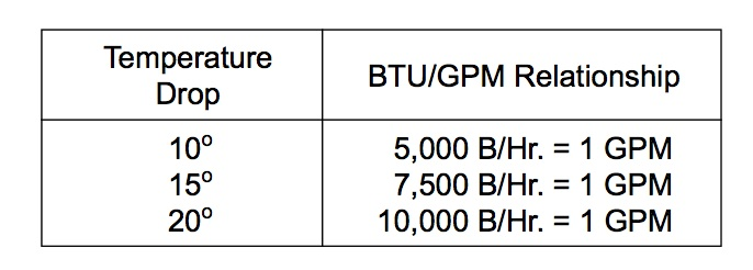
quite small. Thus, recirculation pumps are typically quite small. Table 1 shows the
relationship between temperature drop (∆T) and BTU/Flow.
Table 1

Table 2 shows the relationship between heat loss and lengths of various types of piping. Insulation copper pipe is the most relevant to this discussion.
Table 2

Keep in mind that length of the return recirculation piping is not included in the heat loss calculation and does not impact the pump flow rate. We are really on concerned with getting sufficiently hot water to the most distant fixture and the return line is a one-way trip back to the water heater anyway.
Instantaneous Heaters Require Higher Recirculation Flow Rates
The type of water heater (tank-type or instantaneous) will impact your pump selection. Instantaneous heaters can require a higher recirculation flow rate in order to maintain stable temperatures, therefore your pump selection will be based on a minimum flow through the instantaneous heater rather than the heat loss in the supply pipe. If you are using steam as the energy source than the instantaneous heater recirculation flow rate should be increased to about 25% of the design flow rate to provide stable temperature control during periods of light load.
Pump Sizing Example
Designing a domestic hot water recirculation system is not typically difficult. In fact, we see the exact same model recirculation pump used in application after application without incident, as this one pump is typically able to meet the minor head and flow requirements of most recirculation systems. That said it is important to work through the proper design procedures for any recirculation system. A little time up front can save a lot time (and money) after the fact.
First, it is important to remember the objective of your design, which is to overcome the heat loss in the pipe between the water heater and the most distant fixture during periods of no draw. Think of the recirculating portion of the system as an extension of the hot water storage. The greater the storage volume, the more BTUs that are required to keep the water hot. How many BTUs depends on the following factors:
- The maximum temperature difference (Delta T) that you are willing to tolerate between the heater and the last fixture. This is typically 10°F, 15°F or 20°F.
- The return portion of the recirculation piping need not be considered, as that heat loss occurs after the last fixture, and will not impact the supply water temperature.
The return portion of the recirculation piping need not be considered, as that heat
loss occurs after the last fixture, and will not impact the supply water temperature.
Recirculation Design Example
Let’s work through a simple example based on the design parameters of the apartment building shown here:
With this information show here we can determine our required recirculation flow rate, size our recirculation pipe, and select the right size pump.

Determine Recirculation Rate. The recirculation rate is based on the heat loss that would occur between the heater and farthest fixture at no draw. To determine this value we consult a piping heat loss chart (Table 1). Remember, the values listed here are per 100 ft. so we apply our actual values, we will divide by 100.
Table 1

For this design, a 10°F temperature drop has been chosen. Table 2 shows us what
the BTU/GPM relationship is for the various temperature drops.
Table 2
Next, based on using insulated copper tube, with 25 ft. length between risers, we can manually calculate the total supply line heat loss from the heater to the farthest riser, coming up with a total heat loss of 9320 BTUHs.
With this information we can complete our calculation to determine the necessary recirculation flow rate required to overcome the heat loss in this particular system. Since 1 gpm will convey 5000 BTUH at a 10°F ∆T, the recirculation flow
rate is:
9320 BTUH/5000 = 1.87 gpm
Size the Recirculation Return Line. A sizing calculator (i.e. System Syzer) can be
used to size the return line. For 1.87 gpm we would choose a ¾” copper pipe. The
friction loss for this diameter supply pipe will be about 1.4 ft per 100 ft., according
to the System Size.
Determine Pump Head & Select Pump. Given that our recirculation line is 300 feet in
length, and our flow rate is 1.9 gpm (rounded up), we must calculate the total
friction loss:
Pipe pressure drop = 300 ft. x 1.4/100 = 4.2 ft.
Check valve pressure drop = 1.0 ft.
Supply Pipe (negligible) = 0
Water Heater (negligible) = 0
Total friction head loss = 5.2 ft.
Now it is a simple mater of consulting a manufacturer’s pump curve to select our
pump for 1.9 gpm at 5.2 feet of head.
Admittedly, it’s quite a few calculations to get to the definitive pump size and sizing
programs are available to do most of the work. Still, it’s important to understand the logic that goes into a properly designed hot water recirculation system, especially as system designs become more complex, as we shall see in some below.
Recirculation WITHOUT a Return Line
Not every domestic hot water recirculation system requires a return line. For residential and light commercial applications, there is another way to save water and maintain hot water at the last fixture. It involves connecting a specially designed recirculation pump to the hot and cold water supply lines at the very last fixture – right beneath the sink.

This fairly new introduction pump plugs directly into a 110/120V wall outlet and is connected to both the hot and cold water supply lines. Inside the pump there is a
temperature sensor and a set point control that allows the user to set the desired
hot water outlet temperature and a differential. When the pump senses that the hot
water temperature has dropped beneath the differential threshold, it activates the
pump.
The pump is connected to both the hot and cold water supply lines beneath the sink and has connections that link it to hot and cold water outlets of the sink. If the hot water supply temperature drop too low, the pump will redirect just enough of the hot supply water into the cold water supply line – basically bypassing the hot water outlet and routing water into the cold water supply until the hot water is back up to temp.
This isn’t just a point-of-use-solution, although it works well as one. This approach actually maintains hot water to all the fixtures, while using very little energy (as little as 14 watts).

A Wireless Option
What if you don’t have an outlet under the sink and don’t want to go to the trouble of installing the wiring for one? The same technology described above is also available in a wireless configuration that puts the pump at the water heater and a battery operated mixing valve under the sink.
The desired hot water temperature at the mixing valve is set remotely with a thermostat dial on the pump, which is located at the water heater. A signal is sent to the pump to begin circulating hot water throughout the system. The valve tempers the cold water at the faucet / tap, providing instant hot water. When the set temperature is reached, a signal is sent to turn off the pump. This prevents continuous pump operation, thus saving energy. The pump can also be set on timerbased operation to allow it to run only during periods of high hot water demand.
Either of these solutions represents a quick fix for households or small commercial applications where maintaining hot water temperature at the last fixture has been a
problem. Because it does not involve the installation of a return line, it is especially
well suited for retrofits.
Maintaining Temperature Control In Systems with Steam Instantaneous Water Heaters
Applying recirculation to domestic hot water systems with steam type instantaneous
water heaters requires a little extra attention. The challenge is temperature control.
Under very low load conditions, instantaneous water heater supply temperatures
may fluctuate rapidly – even dangerously. Here’s why:
During periods of light draw, the heater flow rate may become unstable, fluctuating
between a minimal/no load draw recirculation flow rate and that same flow rate plus
the draw of a single fixture. That’s what happens when a single hotel guest decides
to take a shower at 3AM.
Under these circumstances, the heater control valve/controller senses a sudden drop
in supply hot water temperature, as more supply cold water is suddenly forced into
the heater. If the sensor only senses temperature and not flow, the message to the
valve is simply, “Open wide—we need heat!”
But what happens when you unleash up to 100% of your water heating capacity on
a mere 1.5% of your design load? A major rise in water temperature, likely followed
by wild fluctuations (hunting) in your supply hot water temperature!
Increase Recirculation Flow By 25%
One way to avoid this situation is to increase the recirculation flow rate through the
instantaneous steam heater by 25%. (Consequently you will need to upsize your
recirculation pump.) This increase in flow will allow you to use the water storage in
the domestic piping to help initiate mixing of warm return water with cold supply
water as shown in Figure 1. This will improve the light load temperature stability
because with a higher recirculation rate, the controller will see a smaller and slower
change in the hot water supply temperature.
Figure 1

How to Avoid Upsizing Recirculation Piping
Just remember that this change in minimum flow rate can result a rather dramatic
increase in required pump head unless you increase the size of your return piping—
which may or may not be practical depending on the building design.
Let’s say we have an initial 1.9 GPM recirculation flow rate and a friction head loss of
5.2. Head loss varies as the square of flow rate, so if we increase the recirculation
flow rate from 1.9 GPM to 25 GPM, suddenly our friction losses increase to 900 ft.
Required pump heat = (25/1.9)2 x 5.2 = 900 ft.
Clearly, you’d be better off increasing your recirculation pipe size than sizing your
recirculation pump for 900 ft. of head!
Another solution to avoid having to install a 2-inch pipe for your entire recirculation
loop is to install a bypass valve between the supply pipe and recirculation as shown
in Figure below

In this case, the pump provides the necessary flow rate through the heater. Flow
through the balance valve causes the necessary head difference across A to B to
drive the required recirculation flow through the supply piping and back through the
recirculation return. That way only a small portion of piping (between the bypass
and the water heater) has to be sized up for the increase in flow that is necessary to
maintain temperature control.
Domestic Hot Water Recirculation Part 7: Balancing Systems with Multiple Risers
Ever have to wait 2 or 3 minutes (or longer) for hot water to arrive at the shower in
a hotel room? If you know a little about plumbing design you may assume you’ve
had the misfortune of choosing a hotel without a recirculation system. But chances
are the hotel does have a recirculation system, it just isn’t properly balanced. And
you are the lucky hotel guest positioned at the back of the line for hot water.
Why does this happen? Because water always takes the path of least resistance! So if a recirculation system lacks any sort of manual or automatic flow balancing devices (aka flow limiters), hot water will always serve the closest circuits first and/or, if the hotel has more than one return line, the section with the shortest return line.
Automatic flow control valves or manual balancing via circuit setters equal out the
resistance among all these circuits, so no one gets left out in the cold, regardless of
time of day or load. If the option is there, we always recommend automatic flow
control devices for multi-riser systems. These valves arrive from the factory already
customized for a given flow application. You install them and forget about them.
Regardless of the balancing method you select, here are a few things to keep in mind when it comes any multi-riser system:
Only LEAD FREE devices meet code. This requirement, originating with the California Assembly Bill 1953 and part of Standard NSF-61, applies to any pipe, plumbing fitting or fixture used to dispense water for human consumption. As of January 1, 2010 the term “lead free” in this instance refers to the weighted average lead content of the wetted surface area of these devices, which must be not be more than 0.25%. Circuit setters, flow limiters, etc. must be lead free!
You may need to upsize your circulation pump. When balancing multiple circuits, you may need to upsize your recirculation pump just slightly in order reach the minimum flow requirement of any automatic flow control devices that are used. Typically these valves need at least 2 PSI of differential to operate.
Consider using ¾-inch pipe instead of ½ inch. Although your pipe sizing calculations may indicate that you can use ½-inch piping, sizing up slightly gets you a little closer to a balanced system. This is because it helps balance out the pressure drop between the various circuits.
Manual balancing may require some touch. Whenever possible, JMP always recommends automatic flow balancing devices. However, when manual balancing
must be used, many people use a hands-on balancing method.This means physically
touching each riser pipe at start-up, starting with the most distant riser, and tweaking each circuit setter until the pipe feels warm. Once you know you have hot water at the last riser, you then repeat the process, touching all remaining risers and adjusting circuit setters until every pipe in the system is warm.
This is especially helpful on low flow systems with ½-inch circuit setters. Remember, to read a circuit setter, you must first measure the pressure drop between the inlet and the outlet; however, this value may be so slight that it really isn’t a useful point of reference for setting the device. The touch method is fool-proof.
You can ignore vertical lifts when calculating head losses. When determining the head loss in individual circuits that involve both single story and multi-story service, remember that vertical lifts need not be considered, as this head loss is recaptured as the recirculation water returns by gravity. Thus, even though there is an “uphill” service in the multi-story wing of the hotel shown in Figure 1, the single story wing actually has a higher head loss. There is more friction loss at the end of that circuit, than there is at the end of the multi-story circuit. Ultimately it comes down to the pressure drop in each length of the recirculation piping.
Figure 1

Proper Application of Pressure Reducing Valve
Pressure reducing valves (PRVs) are a necessary component in just about any domestic hot water system served by a high-pressure domestic water supply main. In this blog we’ll discuss how to apply PRVs properly so that these “necessary components” don’t become necessary evils that create water service problems and huge energy penalties for owners.
Never EVER Recirculate Thru A PRV!
PRVs are used to reduce high-pressure domestic water supply to more moderate pressures suitable for domestic water service. Typical domestic water systems
require pressures between approximately 25 lbs. (the minimum pressure required to
flush the average toilet) and 80 lbs. (the highest pressure allowed by plumbing
code). For shower service, sink service, etc. it is best to keep pressures below 60
lbs., both for human comfort and the overall functionality, efficiency, and durability
of the system.
This presents certain challenges in recirculation systems serving Highrise buildings – the main one being how to avoid recirculating hot water through a PRV (BAD!)
while still keeping pressures within a suitable range to all floors.
Let’s say we have a 20-story hotel with a single recirculation loop like the one shown
in Figure 1.
Figure 1

Notice the pressure gauge readings at various points in the building. Water enters at 120 lbs., goes through a single water heater and up the riser. Around the 10th floor, flow is divided between the lower and top levels of the structure. At the 10th floor and below, water pressure is at 70 lbs. – too high for shower service so a PRV is installed to absorb 50 Lbs. of pressure, reducing service water to the lower level floors to 20 lbs. Meanwhile, the top 10 floors of the building are serviced with the remaining 70 lbs. of pressure, ultimately reaching the very last fixture at 20 lbs. of pressure.
All would be well, except for the fact that this is a recirculating system, and when the recirculation flow from the top 10 floors meets up with the flow from the lower 10 floors, the latter experiences a bit of a roadblock in the pipe. We now have 70 lbs. pressure water trying to flow into 118 lbs. pressure water. Since there’s no way 70 lbs. can flow into 118 lbs., only the top 10 floors of the building are achieving recirculation. The lower 10 floors are thus starved of hot water recirculation! The hotel guests will have to dump water down the drain until the open fixtures create enough demand to get hot water from the hot water supply main.
In short, the recirculation design shown in Figure 1 will never keep all the hotel guests satisfied.
Larger Pump Not the Best Answer
A quick (but costly) fix to this problem is to add a balancing valve to the recirculation pipe coming down from the top floor, slowing the flow from these floors so that the pressure drops from 118 lbs. to 68 lbs. (Figure 2). This is just enough pressure drop in the return loop to allow return flow from the lower levels to enter into the recirculation loop and back to the pump.
Figure 2

But this creates another problem. With a suction pressure of only 68 lbs. at the pump, we’ll need a higher head pump to raise the pressure above the 120 lbs. required by the water heater. In fact, we’ll need a pump (or two pumps in series) that can deliver 122 feet of head at 6 gpm. That adds up to a lot of additional energy consumption for the life of the system.
Create Separate Pressure Zones!
A better solution is to create separate pressure zones every seven to eight stories, each with its own pump and water heater. Obviously, this may not be an option if the original design was more akin to what we see in Figure 1, but it is the way most hotels (and other similar highrise buildings) are designed today. And it works.
Figure 3

Figure 3 shows how creating separate pressure zones solves the problem. Notice that the recirculation loops for the upper and lower levels of the building now operate independently of one another, and that neither has to pump through the PRV. Rather, the PRV is installed between the cold water supply and the lower level recirculation loop. It is still doing its job, reducing street water pressure into the building as needed, but it isn’t impacting the return flow pressures in any way. The upper level floors, which don’t require pressure reduction because of the static height, operate independently. The lower levels get the required reduced pressures aided by the PRV, but the circulation loop never has to cross over it.